In project 3, the ray-tracing algorithm assumes that light travels in a straight line from the camera into the scene. However, there are sundry cases where a light takes on a non-linear path. For example, on a hot summer day light rays travelling parallel to the ground curves upwards into the sky, causing a non-existent pool of blue to form on the ground. Our project seeks to correctly model these optical effects using a slab based technique and a more flexible Euler integration technique. These algorithms are applied to model optical phenomena - like mirages and Fata Morgana – as well as ray trace scenes through lenses with unique optical properties.
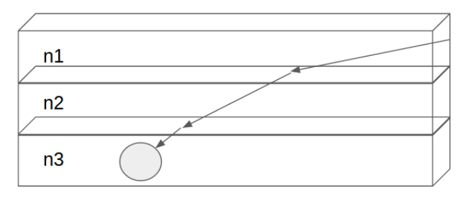
In this method, we model the change of air density using horizontal slabs. Each slab is of equal height and each of the slab represents a different index of refraction. To get the pixel value for a particular position on the image plan, we shoot a ray from that position into the scene. The ray travels in a straight line until it hits the boundary of the slab. We then use Snell's Law to calculate the new direction. This ray tracing continues until the ray either hits the boundary of the scene or a primitive in the scene.
|
|
While the slab method mentioned above is more intuitive, it holds a major problem. In order to generate a relatively accurate image (in comparision to the Euler Integration Technique mentioned later in the report), it requires a large number of slabs. Each transition between slabs require a snell's law calculation, hence it takes a long time to render.
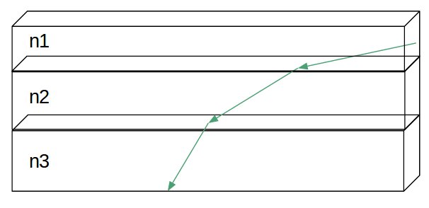
Instead of fixing the height of the slab, we can fix the ray length, such that the light is traveling the same distance within a slab. This modified version of the slab method proves to render faster due to the decreased number of slabs. For rays with a smaller angle (with respect to the normal), it corresponds to a larger slab.
|
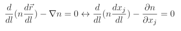
Both slab techniques assume that index of refraction only varies with height. Obviously, this constraint is easy to violate, and ideally our algorithm would still produce viable results even in scenes with complex changes in refractive index. Solving the more general problem requires a more generalized approach. These equations – based on Fermat’s principles and presented by F.J Seron et al. – relate the index of refraction to the slope of a light ray at a point.
|
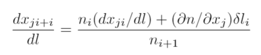
In practice this differential equation can be discretized and solved with Euler integration.
|
Note that this formula can easily be solved iteratively so long as the following quantities are known: the index of refraction and light ray slope at the last time step, the index of refraction at current time step, and derivative of the index of refraction function with respect to position.
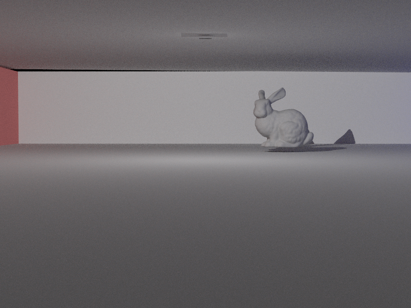
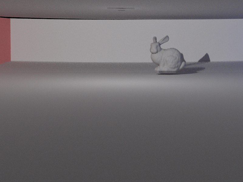
For reference, below is an image rendered using constant index of refraction throughout the scene.
|
Below are images generated using 10, 100, and 700 slabs respectively. The scene modeled using only 10 slabs produces a lot of artifacts. It takes as many as 700 slabs to render a generally accurate image.
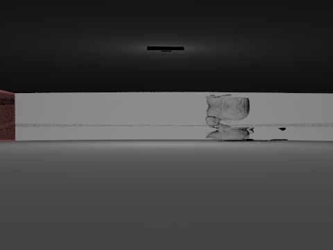
|
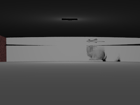
|
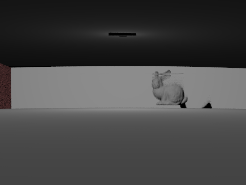
|
|
|
|
In the modified version, the parameter becomes the time that the ray traverses through the scene. In general, with all attributes equal, the longer each ray travels in a slab, the larger the slab. When the scene is modeled with large time steps (ex: 50 units), the scene looks very similar to the constant index of refraction scene. As the time step decreases, distortions start to show.
Note that scenes rendered with time step 1 and scenes rendered using 700 slabs of equal height look similar to each other.
|
|
|
|
|
|
All of the scenes below are rendered with the bottom index of refraction as 1.00

|
|

|
|
All of the scenes below are rendered with the top index of refraction as 1.00
|
|
|
|
|
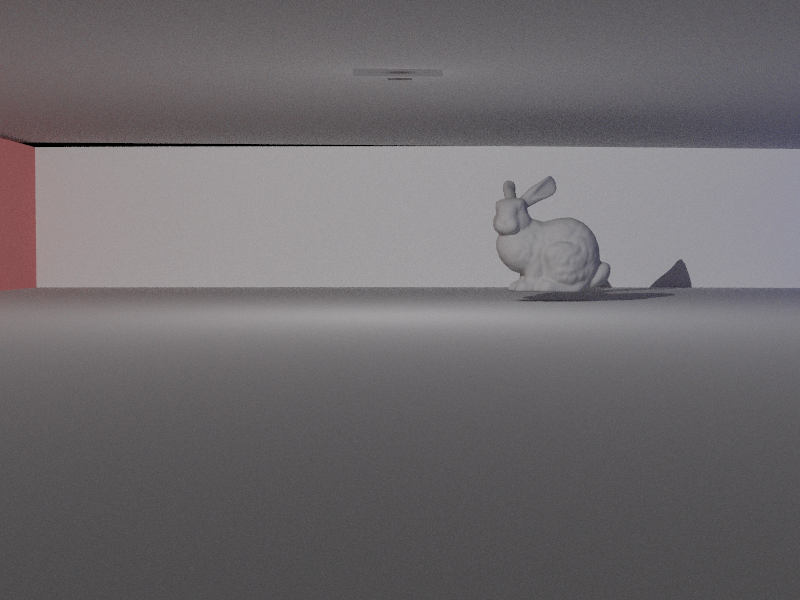
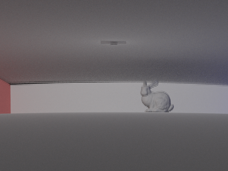
The below images are rendered using different gradient of index of refraction. A mirage occurs when setting the index of refraction to be larger on the botoom. The opposite is true for fata morgana.
Note the change of the surface. In figure 2, due to the change of index of refraction, light bends upward, hence the boundary of the surface is lower than Figure 1. The opposite is true for Figure 3.
Constant Index of Refraction Top index of refraction = 1.00 Bottom index of refraction = 1.00 |
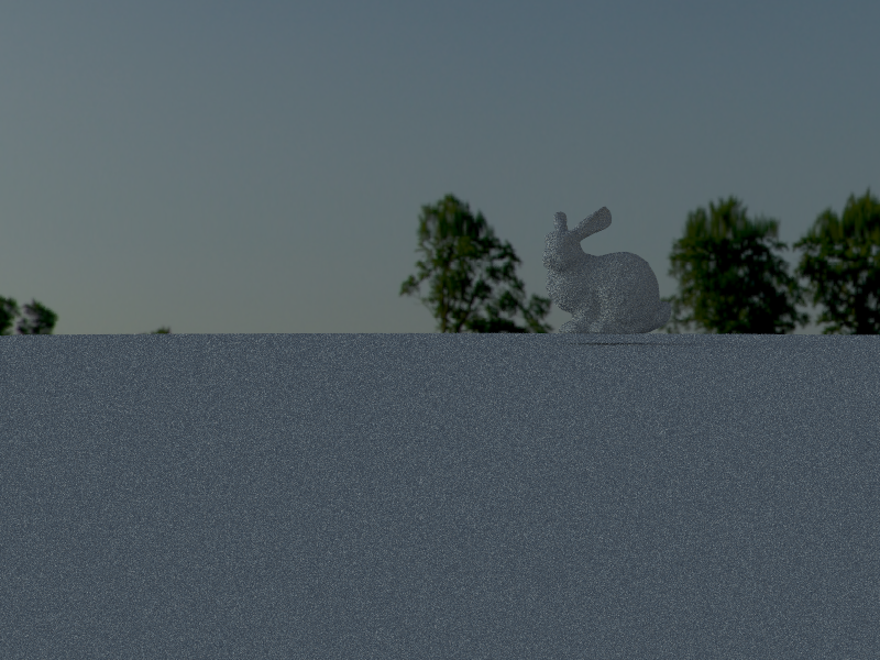
Mirage Top index of refraction = 1.01 Bottom index of refraction = 1.00 |
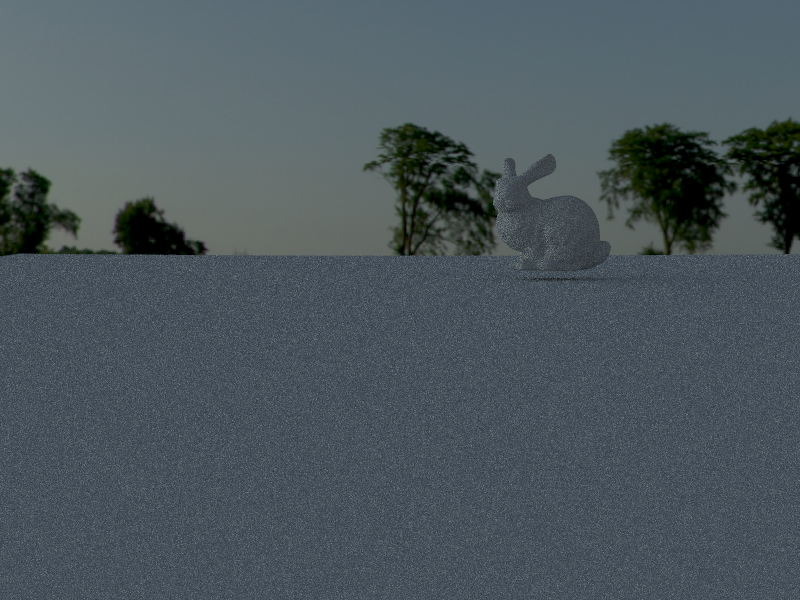
Fata Morgana Top index of refraction = 1.00 Bottom index of refraction = 1.01 |
In order to model heat sources / heat sinks in a scene, we need a way to set part of the scene to have a different index of refraction from the rest. The image below is a demonstration that we can set any box in a scene to have a different index of refraction.
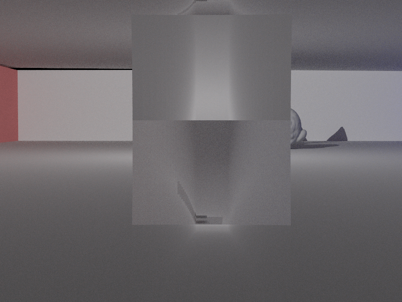
while the rest of the area has 1 as index of refraction. |
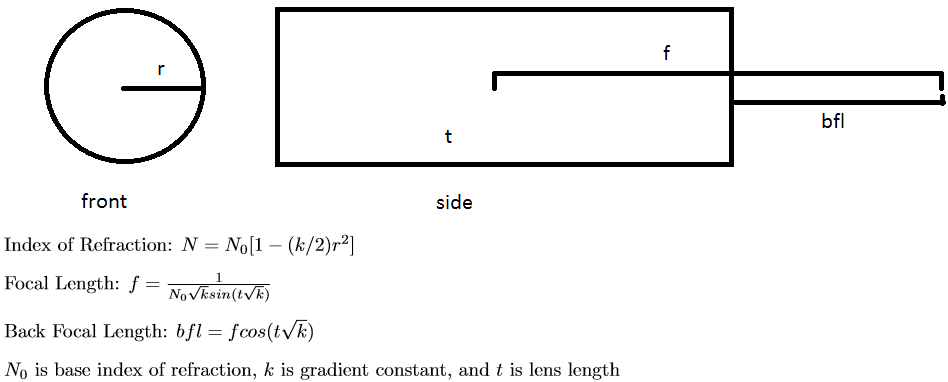
The Euler integration proved to be overkill for simple mirage and fata morgana rendering. Gradient Optics (GRIN) lenses – lenses where the index of refraction changes as a function of position – proved to be the perfect application to test the Euler integration method. Specifically, the ray tracer’s camera uses a cylindrical GRIN lens with index of refraction that varies quadratically as a function of radius.
|
The lens equations above come from the International Society for Optics and Photonics (read more here). Note that the gradient of the above index of refraction equation with respect to (x,y,z) coordinates is:
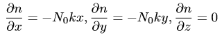
|
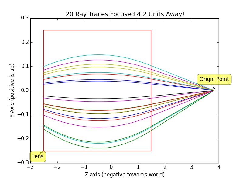
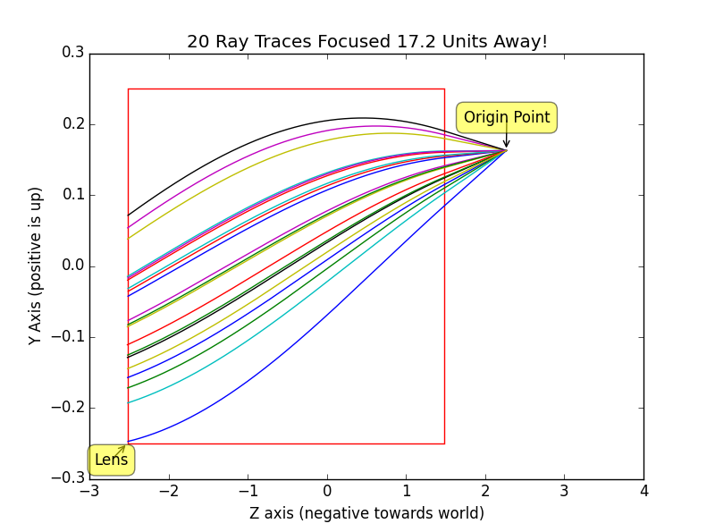
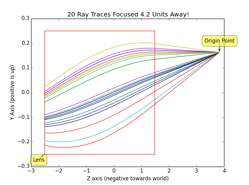
Using this gradient and Euler integration rays can be traced from a point behind the lens out into the front. Below are traces generated by a python script that plot light flowing through the lens from camera position out into the world. The light takes a curved path in a GRIN lens unlike the straight path it would normally take in glass.
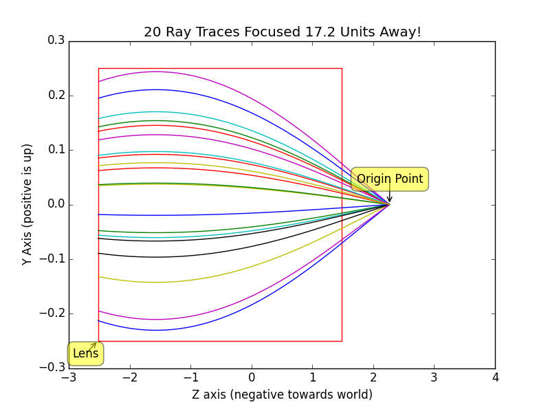
|
|
|
|
All the pieces of the puzzle are ready for building a full ray tracer with a GRIN lens! The Monte-Carlo ray tracing algorithm is modified to account for the GRIN lens as follows: the random (x, y) position is scaled according to FOV parameters and mapped to (-X, -Y, zi) on the focal plane (where zi is displacement of sensor plane solved for by thin lens equation), a random point on lens back plane is sampled at random, a ray is traced linearly from sensor to lens back plane, the Euler integration technique traces rays through the GRIN lens, and finally the light ray exits the lens and is traced as normal. A trace that cannot successfully pass through the lens is returned as invalid and causes a 0 spectrum. This basic technique is very noisy due to many failed lens traces. Thus, random points on the lens are tried until a ray finally gets through to the other side or a max iteration cap is hit. In theory we should be dividing by the number of attempted rays (including fails) when computing the final Monte-Carlo estimation, but empirically doing so generated very dim images. Instead the ray tracer divides by the number of samples per pixel as usual, which correctly brightens the image. This change can be likened to applying a gain to the camera to generate brighter images.
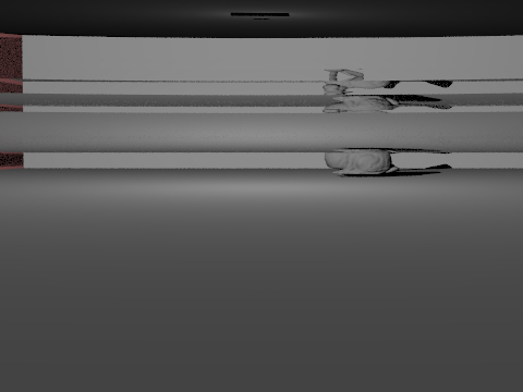
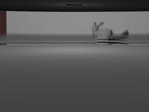
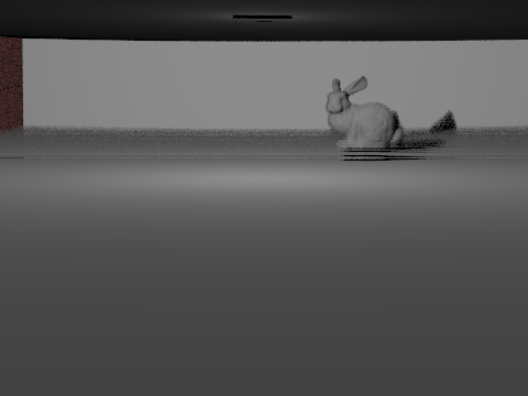
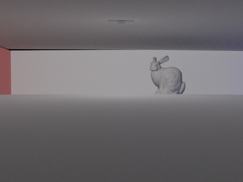
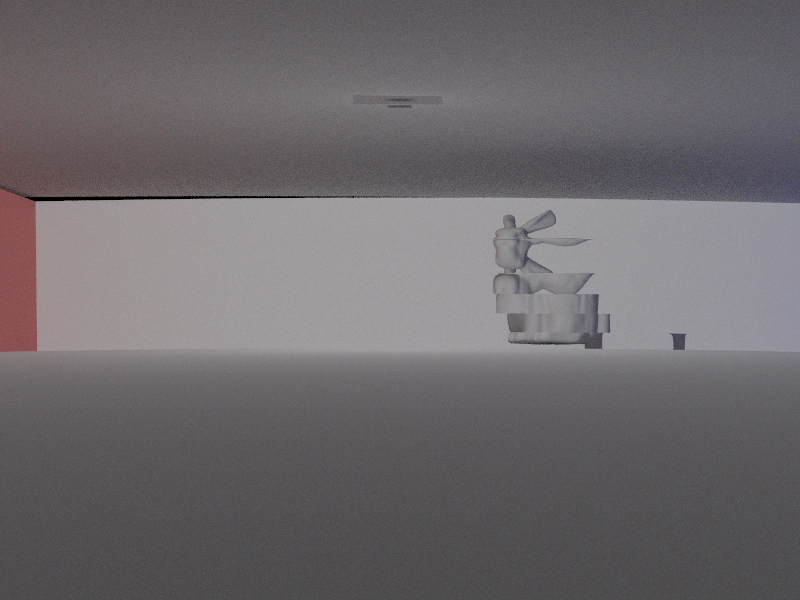
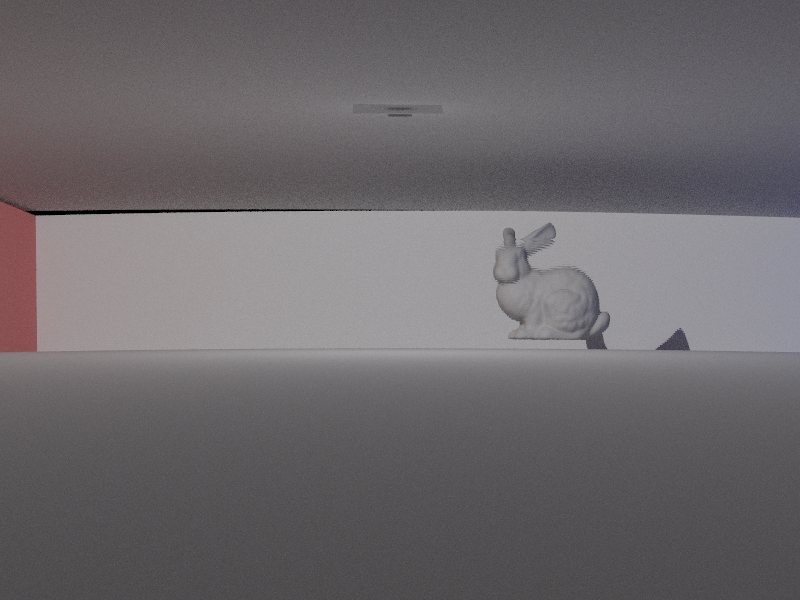
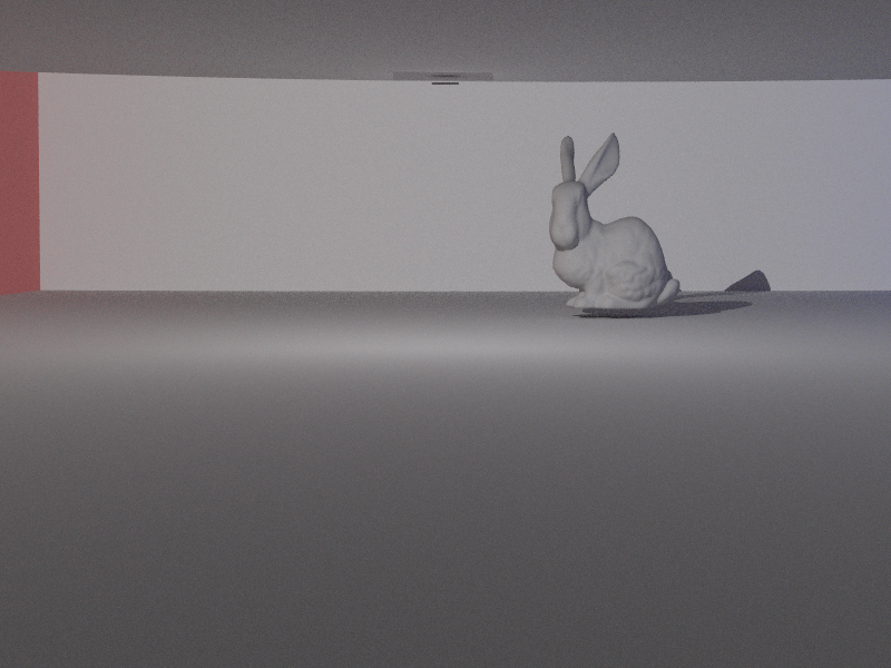
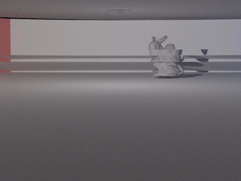
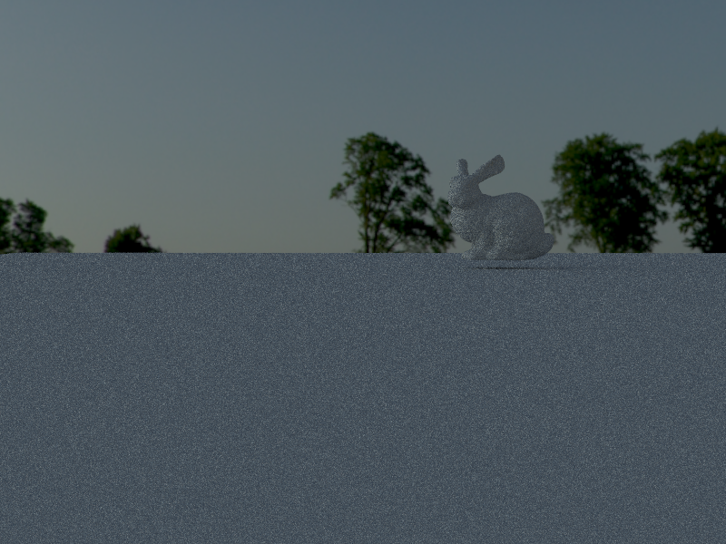
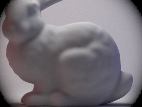
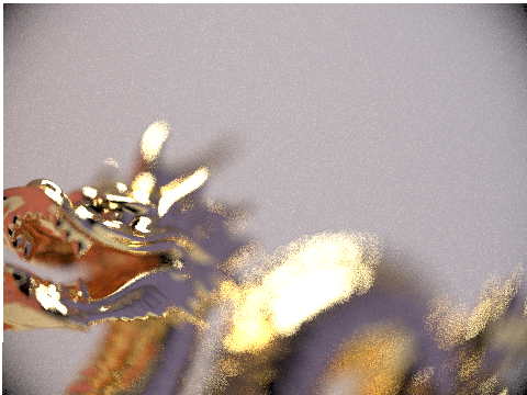
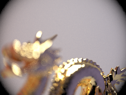
Below are renders of CBbunny and CBdragon using the modified camera and GRIN lens at various quality levels and focused at various depths. Note that the GRIN lens behaves much like a thin lens with no visible aberration! This is pretty impressive considering it is a real physical component. The sensor field of view was chosen to be slightly larger than the lens radius to cause the vignette effect on the sides, where less light gets out to the scene.
| |
|
|
Our video can be found here .
We worked together to get the initial proof of concept working with the slab technique. After that, Jennifer worked on implementing the modified slab technique and generated results for the Fata Morgana and Mirage scenes. Sudeep worked on implementing the Euler Integration technique in code, and generated the GRIN lens results. Both teammates worked on research, and together came up with the direction of the project.
We learned a lot about the research process and taking ideas from theory to fruition. Our topic had a bunch of theoretical literature, so one of the main challenges was finding cool applications that could really showcase the techniques we were implementing. For example, the entire GRIN lens part of our project was entirely unplanned, yet worked as a really cool demo for the techniques we worked on implementing. We learned a lot about debugging graphics applications: especially since it was hard to tell if the blank screen was a result of a programming error or mistake in our math at times. Overall, the final project was a fun experience, and the final renders we got after the research and coding work were supper rewarding.